Add dimming to your 5V "neon" LEDs in ~2 minutes
Dec 25, 2022 — 3 minute read — # Maker # Soldering # LEDsMy friend got this “neon” LED fixture for Christmas! It looks excellent except it’s unfortunately blindingly bright for most situations! Not only is this not ideal for our eyes, it’ll run the LEDs hot and reduce the lifespan of the piece. Depending on how it works, dimming it could be as easy as simply adding a potentiometer across the +5V input.
I had all the parts/tools within arms reach, so why not prototype and test it right now? If it takes less than five minutes to do, don’t leave it for later!
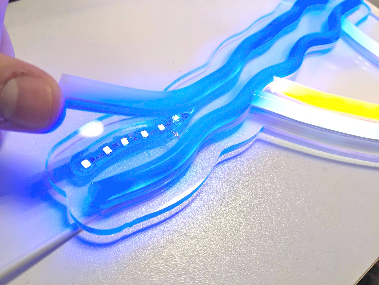
So the strips receive the +5 and GND directly from the USB port. That means the switch probably isn’t hiding any smart components, it’s just a switch! There are resistors across the LED strips to help even out the brightness, but they seem to have selected quite an aggressive amperage/brightness for the fixture as a whole. We could add a single resistor in series with the +5V wire to fix the amperage allowed to flow according to Ohm’s Law:
Voltage(V) = Current(I) x Resistance(R)
So in general, the more resistance we add, the smaller the current will be. The lower the current, the less bright the LEDs will shine. We’ll experience the highest current when the resistance is near zero - which is apparently how these LEDs ship from the factory.
I don’t know exactly what my target current is, so I can’t compute the desired fixed resistance. Wouldn’t it be better anyway to be able to adjust the brightness? A potentiometer is a variable resistor!
With a breadboard, a collection of potentiometers, and my trusty USB -> alligator clip adapters, we can test which potentiometers will give us the nicest gradient of brightness adjustment. All without any modifications to the art piece yet! Our 5V input goes on one side of the potentiometer, our GND in & out goes on the opposite pin. And finally, our 5V output goes on the center pin of the potentiometer.
It works! After swapping a couple different potentiometers, I settled on using a 1K Ohm pot - which seems to give the closest-to-linear brightness adjustment possible.
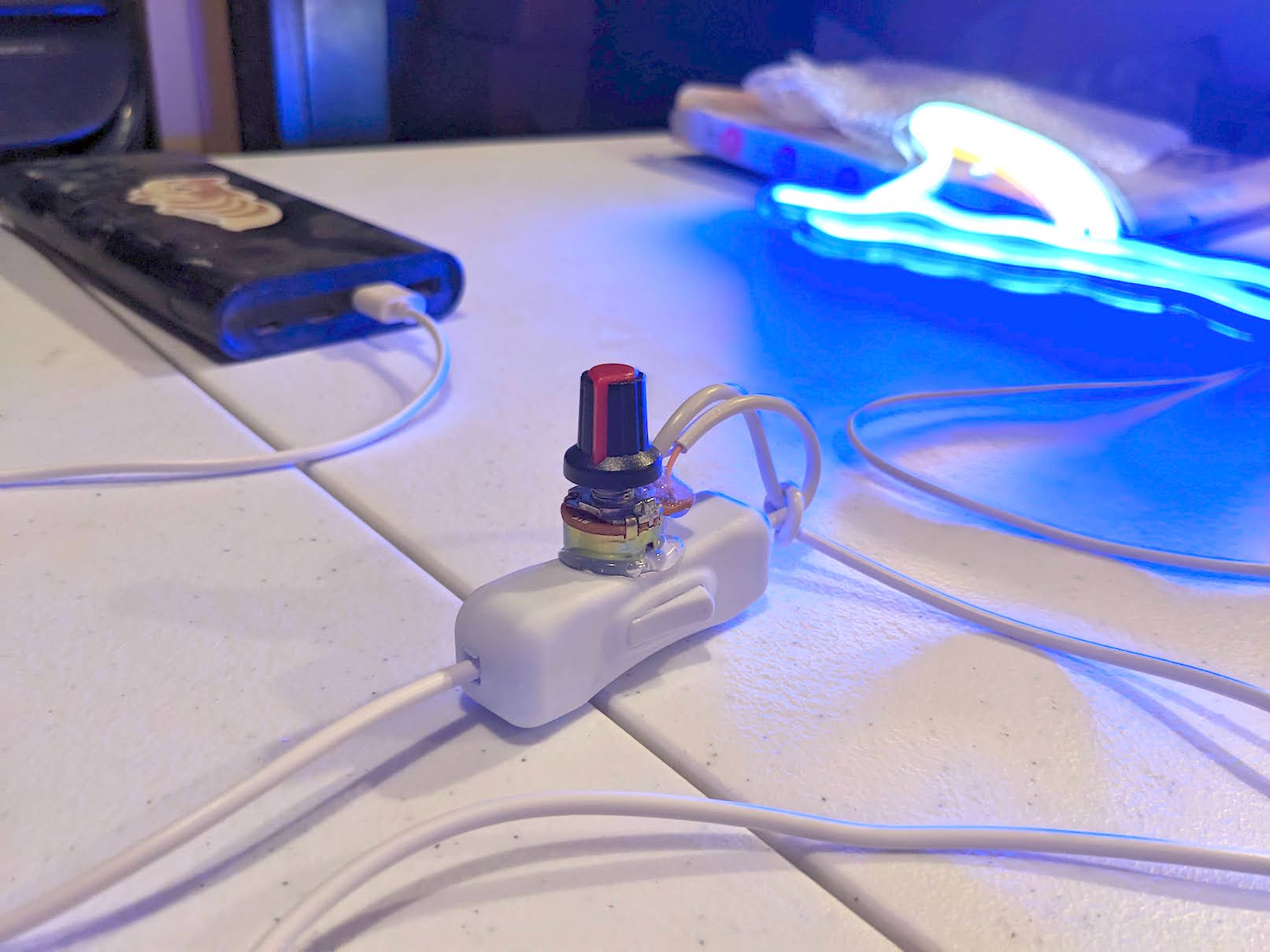
All that’s left to do is snip the wire after the switch, and solder the wires together exactly how we prototyped! I left myself enough room to mount the potentiometer on the switch with some quick-n-dirty hot glue! You can also tie a knot with the cables to relieve strain from your solder joints, and transfer the strain to the switch housing (which I assume is molded to include relief).

And we’re done! Fast, easy, safe, and cheap! It could certainly look a lot less tidy - this is pretty alright for a 2 or 3 minute fix!